Hello, shameless newbie here looking for help with a problem we're having with our laser shows!
We run a laser light show for open days at southampton university and have a rig consisting of a QM2000 pci board which sends differential signals to two CTI 678xx driver boards which control the image x and y-axis via two galvo mirrors. There seem to be several strange issues with the system lately though and I was hoping that someone might be able to give us some pointers.
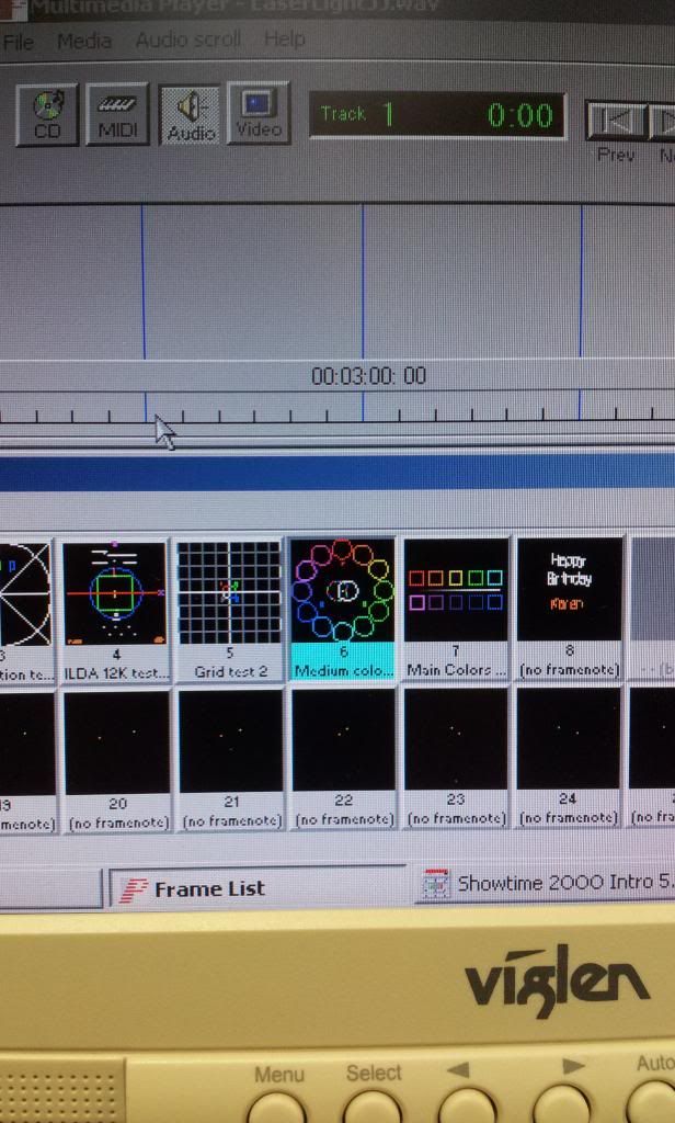
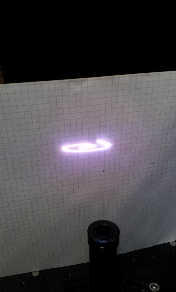
The issue first seemed to arise when connecting up the Lasershow 2000 software and trying to display an image because it became very skewed and distorted.
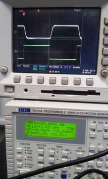
To try and find exactly where the problem was, we connected up the 678xx boards to a differential square wave input instead of the software, and looked at the mirror response to the inputs (across TP1 & TP2 on the boards). With the signal set up at 30Hz @ 1Vp-p we noticed that the two mirror responses were mismatched which seemed to suggest that one mirror was responding before the other, causing our skewed images.
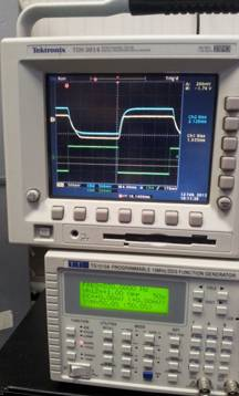
To get over this we decided to go through the tuning process outlined in the drivers user manual, and eventually had them very finely tuned again (see below, green channel is the input square wave, and the blue and yellow are vertical and horizontal mirror responses repectively)…
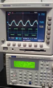
With the mirrors tuned again we scrolled through the frequency range to check the mirror responses at higher frequencies, but we found that as we did this the response of the two planes dropped right off (the square waves became very rounded off), and once again became mismatched. This makes sense with regards to our software signals, because when the laser show is set at very low frequencies we can make out the images, but when increasing the software modulation frequency to the static image range (to the human eye) the images become skewed…
There was also the problem that powering the boards off and back on again resulted in the horizontal mirror becoming offset, almost as if the mirror wasn’t centering itself correctly on start-up. Turning the power off and on again would result in the mirror being offset in a different position. We decided to go through the mirror centering process in the manual again (by using the open loop calibration method for tuning the mechanical angle etc) but this didn’t improve the problem….
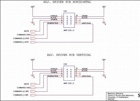
The J1 connector on the driver boards are wired as follows, and the grounds are connected to a star network along with the laser power supplies, so I don’t think there are any grounding issues. The boards are also set to non-inverting differential input on jumper W3 (1&2 and 3&4) and we have tried increasing the rail voltages to +/-28V without any difference …
Switching the connectors over on the mirrors makes no difference to the horizontal plane becoming offset or the degradation in response over frequency range, which suggests that the problem might be the driver board(s), but we dont want to start replacing parts until weve got someone elses opinion! Weve tried contacting the distributors Laser2000, but they dont supply customer support any more, so we went off to CTI but we're not getting any response from them.
Sorry for the long post, but we're a bit at a loss so any ideas/ input would be greatly appreciated.
TIA")
We run a laser light show for open days at southampton university and have a rig consisting of a QM2000 pci board which sends differential signals to two CTI 678xx driver boards which control the image x and y-axis via two galvo mirrors. There seem to be several strange issues with the system lately though and I was hoping that someone might be able to give us some pointers.
The issue first seemed to arise when connecting up the Lasershow 2000 software and trying to display an image because it became very skewed and distorted.
To try and find exactly where the problem was, we connected up the 678xx boards to a differential square wave input instead of the software, and looked at the mirror response to the inputs (across TP1 & TP2 on the boards). With the signal set up at 30Hz @ 1Vp-p we noticed that the two mirror responses were mismatched which seemed to suggest that one mirror was responding before the other, causing our skewed images.
To get over this we decided to go through the tuning process outlined in the drivers user manual, and eventually had them very finely tuned again (see below, green channel is the input square wave, and the blue and yellow are vertical and horizontal mirror responses repectively)…
With the mirrors tuned again we scrolled through the frequency range to check the mirror responses at higher frequencies, but we found that as we did this the response of the two planes dropped right off (the square waves became very rounded off), and once again became mismatched. This makes sense with regards to our software signals, because when the laser show is set at very low frequencies we can make out the images, but when increasing the software modulation frequency to the static image range (to the human eye) the images become skewed…
There was also the problem that powering the boards off and back on again resulted in the horizontal mirror becoming offset, almost as if the mirror wasn’t centering itself correctly on start-up. Turning the power off and on again would result in the mirror being offset in a different position. We decided to go through the mirror centering process in the manual again (by using the open loop calibration method for tuning the mechanical angle etc) but this didn’t improve the problem….
The J1 connector on the driver boards are wired as follows, and the grounds are connected to a star network along with the laser power supplies, so I don’t think there are any grounding issues. The boards are also set to non-inverting differential input on jumper W3 (1&2 and 3&4) and we have tried increasing the rail voltages to +/-28V without any difference …
Switching the connectors over on the mirrors makes no difference to the horizontal plane becoming offset or the degradation in response over frequency range, which suggests that the problem might be the driver board(s), but we dont want to start replacing parts until weve got someone elses opinion! Weve tried contacting the distributors Laser2000, but they dont supply customer support any more, so we went off to CTI but we're not getting any response from them.
Sorry for the long post, but we're a bit at a loss so any ideas/ input would be greatly appreciated.
TIA
 .
. , a picture of the projected image sure would be helpful